Electronic page.
These page will reflect my interest in the field of electronics. Some of my projects will be featured. Some information about microprocessors will be displayed and my experience with them.
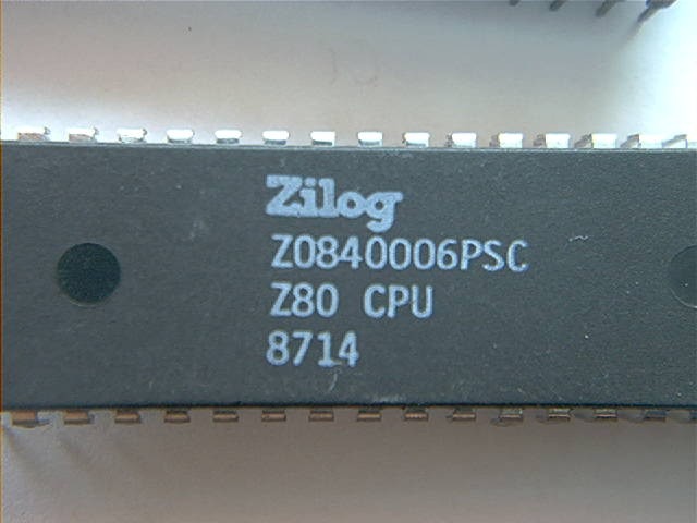
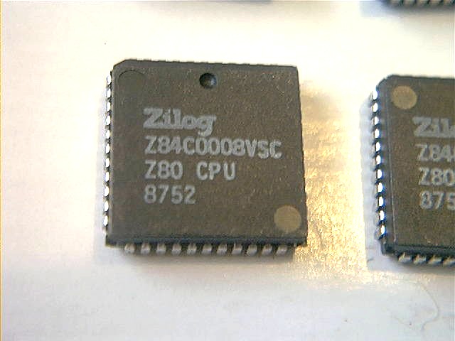
Z80 Processor.
I started my interest in digital electronics with the release of the Sinclair Z80 computer. This little computer was sold as a kit. I acquired mine in 1980. It featured a Z80 processor, 1k or static ram, basic in rom and a multitude of ttl chips. Programs were loaded using audiocassettes. The keyboard was small and cumbersome to use. But, the price was right. A computer for $99.00!!!!. The Z80 was made by the people at Zilog. These engineers had left Intel to create their own company. The processor was a great success. It was much better than the Intel offering, the 8080. It is still widely used because the abundance of programming tools, much of which is free today. Newer versions run faster and its memory addressing capabilities have been increase. The new generation of processors run up to 50 Mhz and can address several megabytes of ram.
Pic tachometer project.
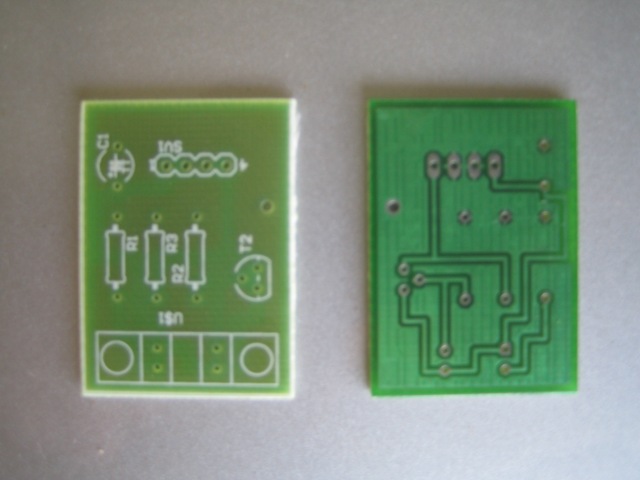
Due to my interest in metal working and machine tools, I decided to build a tachometer for my Sherline lathe. I began researching the project by seeking information in the web. Most information found, related to circuits capable of counting radio frequencies. The ham radio aficionados had a plethora of information. Most of their designs were based around pic micros. Loaded with this information I went to the drawing board and began to build my circuit. After a couple of weeks, my project saw the light and a pcb was manufactured. The design was good and no mistakes were present. The software took just a day or two. Using the C language, the routines were easy to implement. I have taken some pictures that show the progress of this project.
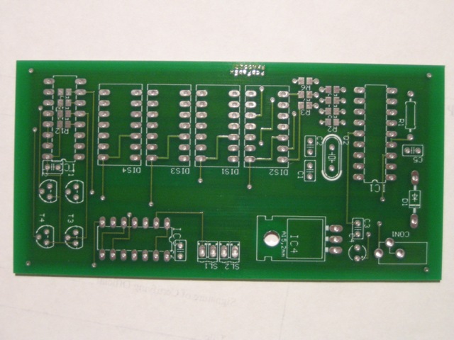
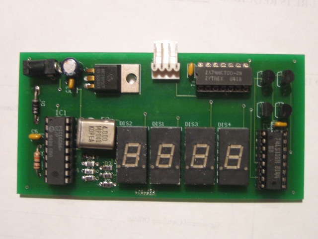
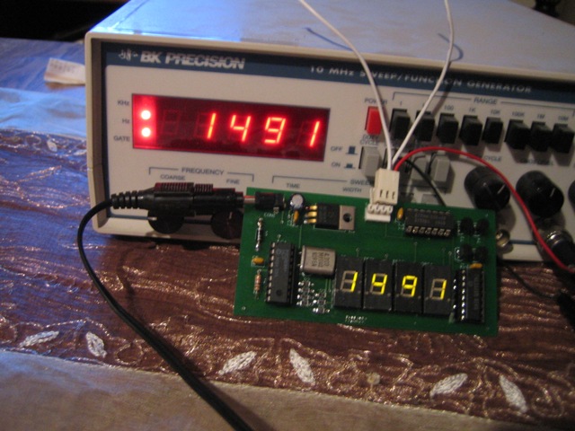
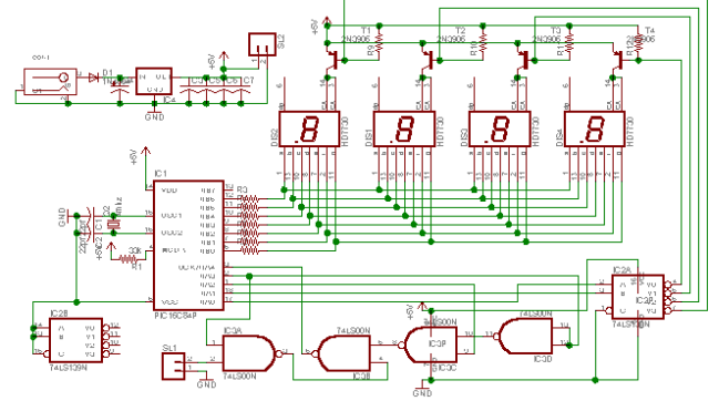
The first picture shows the bare printed circuit board. The next picture shows the board assembled. The last picture shows my creation displaying a known frequency from a commercial signal generator. Both displays show the same frequency. Not bad!!! After my design goes through a rigorous testing face in my hot garage, I may offer the bare pcb for a nominal fee to cover manufacturing expenses. The size of this board is about 2 by 4 inches. The code will be offered free. You can program your own pic microcontroller or I can sell you one programmed for a nominal fee. It uses a 16c84 micro running at 4 mhz. Four 7 segment led displays, four pnp transistors, two ttl ic's and a few resistors and capacitors is all that is needed. If there is enough interest, a full kit may be offered. The schematic can be seen here.
Optical interrupter switch.
To be able to measure spindle speed, a small circuit board was designed. There are many different ways to do this. You can use a Hall effect switch (HES), that has the property of detecting a magnetic field near it. A small magnet is place in the spindle and the HES is placed in a location where the magnetic field could be sensed. As the spindle rotates, the magnet gets near the HES and the switch is activated. Each time the magnet passes by, a pulse is generated. Another way to do it, is using some form of photo detection using a light emitting diode and a photo sensitive device. Most commonly a photo transistor. One circuit uses a photodiode which is placed opposite to a photo detector in a case. The two are separated by a gap. A wheel with an evenly spaced number of holes, slots, would be attached to the spindle. As the spindle rotates the beam of light from the emitter is interrupted. Each time this happens a pulse is generated. In the final example the emitter-detector combo is placed side by side. If a reflective surface is placed in front of this unit, the reflected light would be picked up by the detector. That would turn it on, generating a pulse. A wheel with a specially designed pattern of opaque, dark and reflective, white surfaces is placed on the back of the spindle. Each time the light is reflected, a pulse is produced. In my case I am using the opto interrupter switch (OIS). A Harris H21A1 OIS is placed in a small pcb near the spindle and a wheel with a slot(s) is placed on the spindle. As the wheel rotates, the slot(s), let the light pass through turning the detector on. Each time this happens, a pulse is produced.
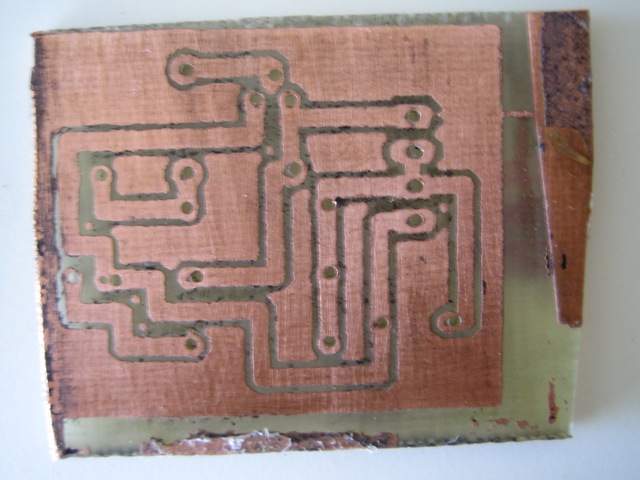
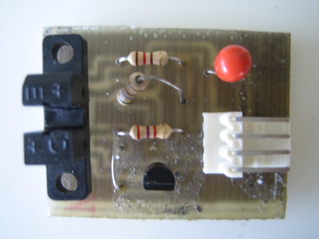
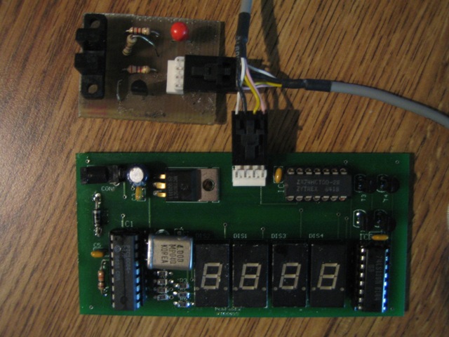
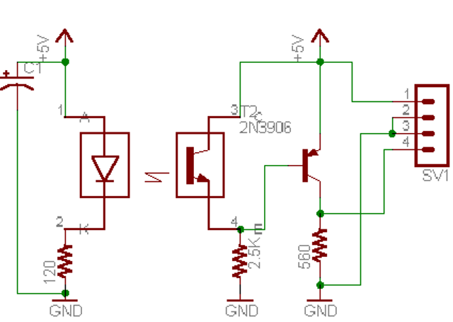
First picture shows my prototype after etching. Not very pretty, but it does the job. Second picture shows the board assembled. The OIS can be seen on the left of the picture. Third picture shows the optoboard (tm) and counter connected together with a small cable. The cable has 4 conductors that carry 1) 5 volts, 2,3) ground 4) signal. Testing in my lathe proved the circuit works as expected. Ideally a wheel with 10 slots would be used as to improve the accuracy at the low frequencies. The schematic can be seen here here. As per the datasheet on the opto interrupter switch, the diode is biased with a 120 ohms resistor. For best transfer, the resistance in the npn output transistor is specified at 2.5k. The transistor is constantly on, unless the beam is interrupted. As the npn output transistor is always on, over 4 volts are present at its emitter. This voltage (>4) keeps the pnp transistor off at all times. Its output, taken from the emitter is at ground level. When the opto switch beam is blocked, the npn output transistor stops conducting. This causes its emitter voltage to drop to ground level. This forwards biases the pnp output transistor into full conduction. The output goes up close to the power supply (Vcc minus the saturation voltage). The printed circuit can be seen here
Finally I got some boards professionally made. They are single sided an about 1.5 X 1". If you are interested, I will sell these assembled for $10.00 which includes the shipping. The optoboard can be used as a limit switch or as the sampling board for the tachometer. it's max frequency response is around 16,000 Hz. How does it look?. Well, look at the picture above of the prototype. That is what it looks like.